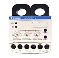
| Items |

TSBSB05
TSBSB Shock Relay for Overload Protection
|

TSBSB10
TSBSB Shock Relay for Overload Protection
|

TSBSB30
TSBSB Shock Relay for Overload Protection
|

TSBSB60
TSBSB Shock Relay for Overload Protection
|

TSBSB100
TSBSB Shock Relay for Overload Protection
|
|
Transformer
|
N/A
|
N/A
|
N/A
|
N/A
|
N/A
TSB2CT100
|
|
Motor
|
N/A
|
|
Motor HP 230 VAC
|
N/A
1/8 to 1 hp
|
N/A
2 to 3 hp
|
N/A
5 to 7 hp
|
N/A
10 to 15 hp
|
N/A
20 to 25 hp
|
|
Motor HP 460 VAC
|
N/A
1/4 to 3 hp
|
N/A
3 to 5 hp
|
N/A
7 to 15 hp
|
N/A
20 to 30 hp
|
N/A
40 to 60 hp
|
|
Operation Power
|
N/A
24 to 240 V AC/DC +/- 10%, 50/60 Hz
|
|
Maximum Motor Voltage
|
N/A
600 VAC at 50/60 Hz
|
|
Load Current Setting Range
|
N/A
0.5 to 6 A
|
N/A
1 to 12 A
|
N/A
3 to 30 A
|
N/A
5 to 60 A
|
N/A
10 to 100 A
|
|
Trip Output Relay Status - Energized/Fail Safe to Open
|
N/A
Manual Setting
|
|
Trip Output Relay Status - Energized/Fail Safe Close
|
N/A
Automatic Setting
|
|
Trip Output Relay Contact Rating
|
N/A
3A Load
|
|
Start Time Setting Range
|
N/A
0.2 to 10 arc·sec
|
|
Shock Time Setting Range
|
N/A
0.2 to 5 arc·sec
|
|
Input Voltage for Operation
|
N/A
|
|
Allow. Input Voltage Fluctuation (Full Scale)
|
N/A
10 %
|
|
Meter Fine Tuning Adjustment
|
N/A
|
|
Output Contact1
|
N/A
3A/250 VAC, Resistive
|
|
Test Button
|
N/A
Yes
|
|
Test Function
|
N/A
Built In
|
|
Withstanding Voltage
|
N/A
2000 VAC, 5 mA at 60 Hz for 1 min. between terminal and enclosure
|
|
Surface Color
|
N/A
|
|
Weight
|
N/A
0.440 lb0.20 kg
|
N/A
0.440 lb0.20 kg
|
N/A
0.440 lb0.20 kg
|
N/A
0.440 lb0.20 kg
|
N/A
1.540 lb0.70 kg
|
|
Shock Relay Power Supply
|
N/A
90 to 240 VAC
|
|
Power Consumption (or less)
|
N/A
2 W
|
|
Operating Temperature Range
|
N/A
-4 to 140 ºF-20 to 60 ºC
|
|
Max. Elevation
|
N/A
2000 m6500 ft
|
|
Operating Humidity
|
N/A
45 to 85% R.H. with no condensation
|
|
Atmosphere
|
N/A
Free of corrosive gas and dust. Pollution degree 3 or below when installed in control box
|
|
Protection Rating
|
N/A
IP20
|
|
Construction Material
|
N/A
Material Lower Housing - PA66 Material Upper Housing - PA6 Terminal Cover - PA6
|
|
Industry Standards/Certifications_SYN
|
N/A
CCC - China CE Marking - Europe RoHS Compliant UL/cUL - North America
|
|
Mounting
|
N/A
35 mm DIN Rail or Mounting Plate
|
|
Storage Temperature Range
|
N/A
-22 to 158 ºF-30 to 70 ºC
|


